Table of Contents
Reference Application Components
This section covers the details of the Reference App’s User Interface (UI). Refernece App has multiple section each covering different functionality such as Media player, IO, Video Player, Analog and Ethernet Cameras, CAN Bus section.
The following image represents the tabs of the Reference App and the relative description sections of each:
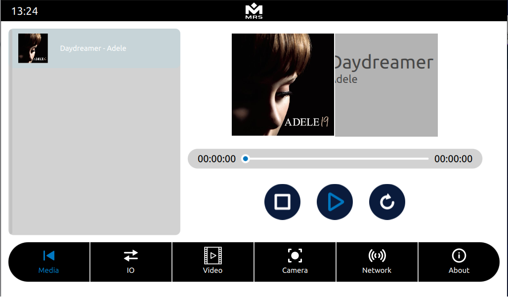
Media player Section
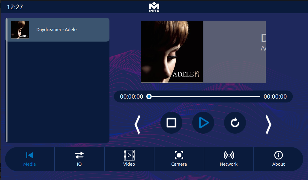
The reference app provides music playback features, including play, pause, stop, and track progress. It comes with a pre-installed song file, and additional songs can also be added in /rw_data/ path in mconn. These song will be displayed in the song list along with cover art and can be played by clicking on it.
 |
|---|
| Media Player |
Refer to Audio Player for more details.
IO Section
The IO section provides functionality for controlling screen brightness, managing the buzzer, operating high-side drivers, and monitoring the values of digital and analog inputs. Details on each are as follows
Buzzer
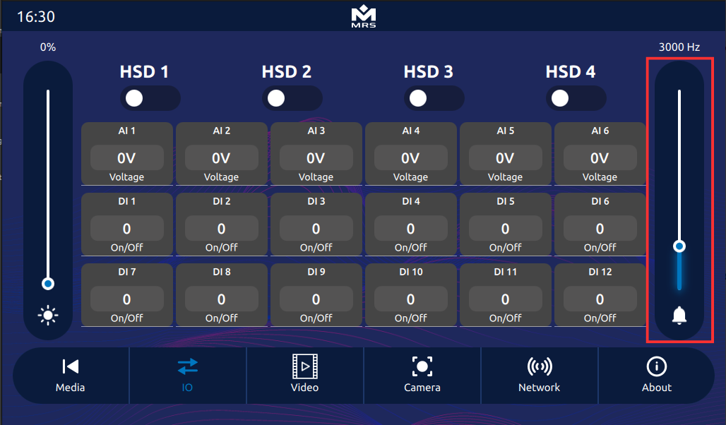
The display is equipped with a programmable buzzer, accessible through the I/O page. Users can turn the buzzer on or off by clicking the bell icon. Additionally, the buzzer frequency can be adjusted using the slider provided above the buzzer button.
 |
|---|
| Buzzer Control |
The following function controls the buzzer and is accessible from C++ and QML:
Q_INVOKABLE void setBuzzer(bool status, uint frequency = 1000);
- status: true to turn ON, false to turn OFF
- frequency: Buzzer frequency in Hz (range: 0 to 15,000, default: 1000)
Brightness
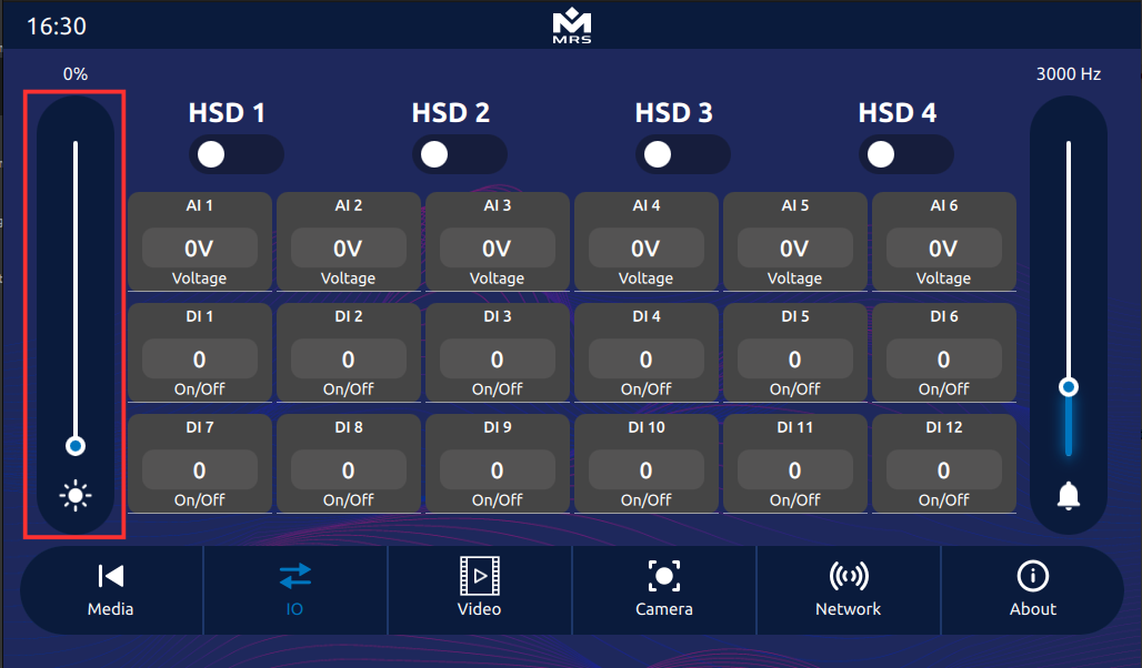
The brightness of the display can be adjusted from the I/O section of the Reference app using the left slider.
Users can set a value between 0 and 100.
 |
|---|
| Brightness Control |
The brightness can also be controlled programmatically using the following function from C++ and QML:
Q_INVOKABLE void setBacklight(uint percent);
- percent: Brightness level from 0 (minimum) to 100 (maximum)
Analog Input
The display is equipped with six 0–12V analog input pins.
The assigned pins for analog inputs on the AMPSEAL connector are: Pins 9, 10, 17, 19, 20, and 22.
(Refer to the figure for physical layout.)
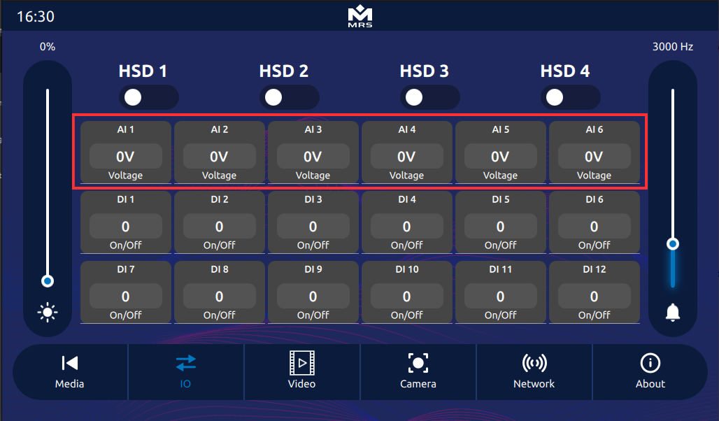
In the UI, these analog inputs are represented by the components AL1 to AL6, each displaying the input voltage in volts (V).
 |
|---|
| Analog Inputs |
In QML, the values of these analog inputs can be accessed through the following Q_PROPERTY declarations:
Q_PROPERTY(double adc1V READ adc1V NOTIFY adc1VChanged)
Q_PROPERTY(double adc2V READ adc2V NOTIFY adc2VChanged)
Q_PROPERTY(double adc3V READ adc3V NOTIFY adc3VChanged)
Q_PROPERTY(double adc4V READ adc4V NOTIFY adc4VChanged)
Q_PROPERTY(double adc5V READ adc5V NOTIFY adc5VChanged)
Q_PROPERTY(double adc6V READ adc6V NOTIFY adc6VChanged)
Digital Inputs
The display is equipped with twelve 0–12V digital input pins.
The table below shows the GPIO numbers assigned to each digital input pin on the AMPSEAL connector.
(Refer to the figure for the physical layout.)
| Pin | GPIO | Pin | GPIO | |
|---|---|---|---|---|
| 1 | 91 | 25 | 140 | |
| 2 | 117 | 28 | 2 | |
| 5 | 124 | 29 | 145 | |
| 8 | 134 | 31 | 116 | |
| 11 | 139 | 34 | 122 | |
| 12 | 144 | 35 | 136 |
In the UI, these digital inputs are represented by components DL1 to DL12, each displaying the state of its respective input.
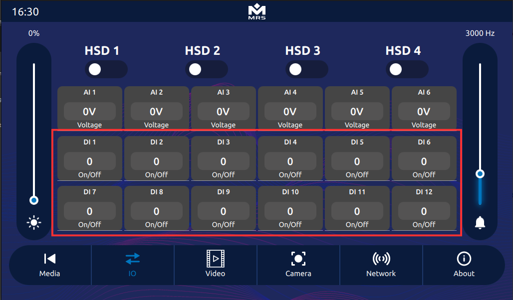 |
|---|
| Digital Inputs |
Digital Output
The display is equipped with 4 digital high-side drivers, each capable of sourcing up to 2A.
The table below shows the GPIO numbers assigned to these digital outputs on the AMPSEAL connector.
| Pin | GPIO | Pin | GPIO | |
|---|---|---|---|---|
| 3 | 162 | 6 | 167 | |
| 4 | 163 | 7 | 200 |
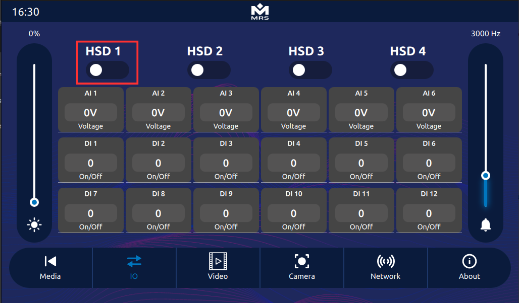 |
|---|
| Digital Out |
The digital outputs can be controlled using the following function, accessible from QML/C++:
Q_INVOKABLE void setDigitalOutput(uint pin, bool value);
-
pin: Specifies which digital output to control. Possible values:-
Io_Q.digitalOutput3 -
Io_Q.digitalOutput4 -
Io_Q.digitalOutput6 -
Io_Q.digitalOutput7
-
-
value: Sets the output state.-
true: Turns the digital output ON -
false: Turns the digital output OFF
-
Refer to IO Module for more details.
Cameras
The Reference app supports both analog and Ethernet cameras for video display.
Analog Camera
The display supports up to 4 analog cameras.
To switch between different camera feeds, simply click on the Analog Stream Video UI element — this cycles through feeds from Camera 1 to Camera 4.
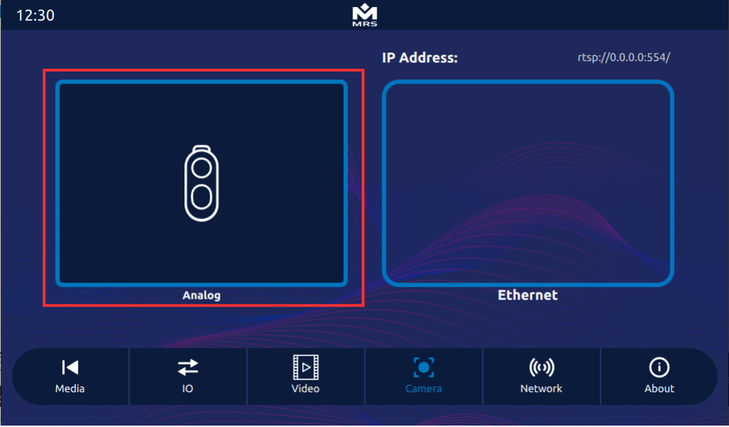 |
|---|
| Analog Camera |
To integrate an analog camera stream in the UI, you need to create an instance of the custom Camera type.
Refer to the MConn Programming Guide for more details.
Example usage:
// Important: You need to import registered types here. In case of Reference app it will be:
import MRSComponents 1.0

Camera {
    id: analogCamSrc1
    type: "analog"
    captureDevice: "/dev/video1"


}

CameraPlayer {
    id: camera3
    source: analogCamSrc1
    anchors.fill: parent

        Component.onCompleted: {
        analogCamSrc1.startStream()
    }
}
- captureDevice: Path to the video input device.
- Possible values: /dev/video0, /dev/video1, /dev/video2, /dev/video3
Ethernet Camera
The display also supports Ethernet cameras using H.264 video compression over UDP/RTP streaming.
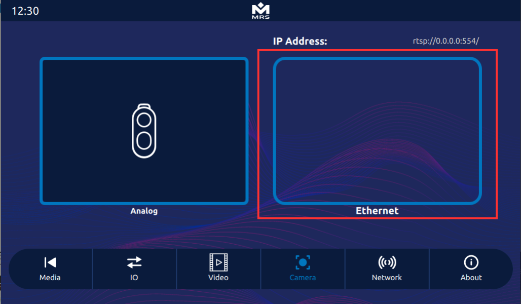 |
|---|
| Ethernet Camera |
(Refer to the MConn guide or specific documentation for configuration details.)
// Important: You need to import registered types here. In case of Reference app it will be:
import MRSComponents 1.0

Camera {
    id: rtspEthernetCamSrc
    type: "rtsp"
    captureDevice: "rtsp://admin:admin123@192.168.1.113:554/cam/realmonitor?channel=1&subtype=0&unicast=true&proto=Onvif"
    userID: "admin"
    password: "admin123"
    dynamicRecordingSaveLocation: "/rw_data"
    recordingFileName: "cam1"


}

CameraPlayer {
    id: rtspCameraPlayer
    source: rtspEthernetCamSrc
    anchors.fill: parent
    visible: true

        Component.onCompleted: {
        rtspEthernetCamSrc.startStream()
    }
}
-
Parameters:
- type: Set to "rtsp" for Ethernet streaming.
- captureDevice: RTSP URL of the camera.
- userID / password: Credentials for the RTSP stream.
- dynamicRecordingSaveLocation: Path to save recorded files.
- recordingFileName: Base name of the recording file.
Refer to Camera Module for more details.
Video Player
The MConn comes with a video player. The Reference App video player holds play/pause and fast forward/rewind video functionalities. The video player supports the following video formats:
- Mp4
- Flv
- Mkv
- 3gp
Following are the commands to use the video player in QML:
  Video {
        id: video
        anchors.fill: parent
        source: "file:///rw_data/samplevideo.mp4"
        autoLoad: true
        autoPlay: false
        fillMode: VideoOutput.Stretch
      }
Refer to Video Player for more details.
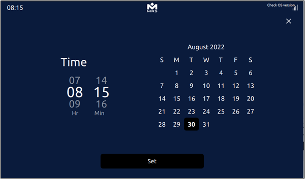
Date Time Settings
The Display comes with the functionality to set date and time. To access date and time setting component, follow the steps below:
- Open Control Panel by swiping down from the top.
- Tap on the Date time button to open the settings panel.
- Set the date and time as per requirements.
- Tap on the Set button to save the changes.
 |
|---|
| Date and Time Component of MConn |
On backend, it uses simple Q_INVOKABLE setTimeDate function that uses the date command of Linux to set user-defined time and date.
| Important |
|---|
| The date must follow the MM/DD/YYYY format. |
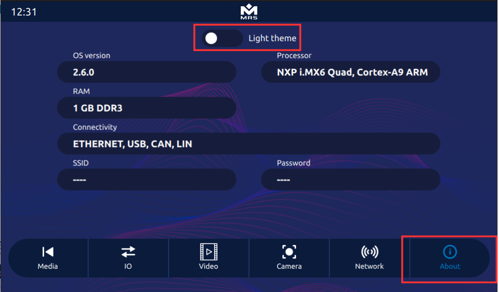
Theme
The MConn Reference App comes with two in-built contrasting themes, which by default, is the Dark Theme.
The variable REF_APP_THEME when set to 0 or 1 corresponds to dark or light theme for the Reference App, respectively. To change the theme of the Reference App, tap on the toggle button in the About tab:
 |
|---|
| Theme Toggle in the Reference App |
The light theme of the Reference App looks as follows:
 |
|---|
| Light Theme of the Reference App |